Verification and diagnosis of a battery module
It is possible to carry out certain checks on a battery module without needing to open it. These checks allow for an assessment of its general condition and the detection of potential operational anomalies.
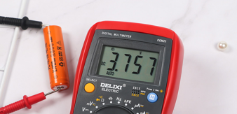
Measurement of open-circuit voltage
Using a multimeter connected to the + and – terminals of the battery, the open-circuit voltage (without any load connected) can be measured.
This value provides information on the overall state of charge of the battery.
Example:
For a 16S LiFePO₄ module, the nominal voltage is approximately 51.2 V, but it can vary:
Minimum voltage: 43.2 V (battery almost discharged)
Maximum voltage: 58.4 V (battery fully charged)
A measurement outside this range indicates a malfunction (damaged cell, BMS in protection, defective connection…).
Measurement of voltage under load
Another method is to measure the battery voltage when a consumer is connected (battery charging or discharging).
The voltage should remain stable and close to the open-circuit value.
A significant voltage drop when applying a load may indicate:
a high internal resistance (ageing of one or more cells),
a connection problem (poor contact or 'hot spot').
To confirm this latter case, a thermal camera can be used to identify overheating areas on the connections.
Diagnosis via communicating BMS
Some modern batteries are equipped with a communicating BMS, accessible via a dedicated application or interface.
This system allows real-time consultation of detailed information about the battery's condition, such as:
the SoC (State of Charge),
the internal temperature,
the number of cycles,
the fault codes or safety alerts (overvoltage, overheating, imbalance between cells, etc.).
This feature facilitates preventive diagnosis and maintenance without dismantling the module.
In summary
| Type of check | Method | Information obtained | Signs of anomaly |
| Open-circuit voltage | Measurement at terminals with multimeter | Overall charge level | Value outside range 43.2–58.4 V |
| Voltage under load | Measurement with connected consumer | Voltage stability and internal resistance | Voltage collapse, overheating |
| Via communicating BMS | Mobile application or dedicated interface | SoC, T°, faults, cell balance | Error codes, unbalanced cell |
*: The technical information presented in this article is provided for guidance only. It does not replace the official manuals of the manufacturers. Before any installation, handling or use, please consult the product documentation and follow the safety instructions. The site Torque.works cannot be held responsible for inappropriate use or incorrect interpretation of the information provided.